

Ballistic Gear Drives Installation Guide
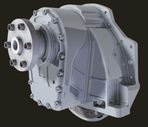
Ballistic Drives is the highest quality gearbox available with redesigned features that offer a lightweight, affordable replacement option for your airboat. Reading and following these instruction guidelines will facilitate easy installation of your Ballistic Drives unit so you can begin enjoying your time on the water.
PARTS KIT
6) Grade 8 7/16 - 20 x 1-1/2” Bolts
6) 7/16 Flat Washers
6) 7/16 Flange Nylock Nuts
One of the following Bellhousing Bolt Kits:
(5) M10 Bolts (LS Engine) with M10 Hi-Collar Lock Washer
(6) 3/8 Bolts (SBC/BBC) with 3/8 Hi-Collar Lock Washer
Ballistic Gear Drives are easy to install, and are provided with everything you need for standard installation
TOOLS NEEDED FOR INSTALLATION
7/16” Socket with Ratchet Drive and 2" Extension
Allen Wrench Set
Blue Loctite
PLEASE AND FOLLOW ALL INSTALLATION INSTRUCTIONS
The following guidelines will help to ensure trouble free installation and operation of your new Ballistic Gear Drive. Failure to properly follow these guidelines may lead to damage to the gearbox, to your airboat, or to yourself, and will also void the warranty of this product.

IMPORTANT NOTE: This unit is shipped dry. YOU MUST ADD OIL PRIOR TO OPERATION!!
*Failure to do so will result in catastrophic failure and void your warranty.*
INSTALLATION INSTRUCTIONS
Step 1
Position the Ballistic Drives unit on dowel pins at the rear of the engine. Assemble two Allen head bolts with two lock washers (one lock washer on each bolt) and start the bolts on each side of the Ballistic Drives bell housing. This will hold the unit in place for proper alignment of the six holes in the flywheel and flex plate.
Step 2
Assemble the remaining Allen bolts and lock washers as described in step 1. Place 1 drop of Loctite (Blue) on each bolt and begin tightening the bolts, alternating side to side to ensure equal draw down of the unit.
Step 3
Using your existing rigging mounting bolts and rubber mounts; assemble one washer to each bolt, place the bolt through the housing, through the rubber mount and mounting bracket, and secure with washer and lock nut. To avoid clearance issues and interference on the inside of the bell housing, install the two mounting bolt assemblies downward through the housing and your mounting bracket and place the lock washer and nut on the bottom side of the mounting bracket. When assembling, take precautions to avoid over-tightening and compressing the rubber mounts.
Step 4
Locate the 6 Grade 8 Steel 7/16 x 20 x 1-1/2” bolts, washers and locknuts to be used for coupling the flywheel to the flex plate on the Ballistic Drives unit. Align all 6 holes and install a bolt WITHOUT washer from the engine side to the Ballistic Drives unit and install the washer and nylock nut. Add one drop of Blue Loctite to the bolt prior to installation. NOTE: The bolt head MUST be closest to the engine block with the nylock nut closest to the gearbox side. Repeat with all remaining bolts, washers, and flange nuts. (If there is an issue with the gap between the flex plate and flywheel being too loose, add a washer as a shim as all bolt assemblies should be snug.) There should not be pressure on the engine flex plate as this will cause pressure on the crankshaft and possible engine damage may occur. Once all 6 bolt assemblies have been attached, torque the bolts to 50 foot-pounds.
The softdrive pattern is machined to alingn to a Heavy-Duty JW Wheel and will bolt up with zero modification. We strongly suggest using a JW Wheel flexplate as the pre-drilled holes align perfectly. A stock flexplate or aftermarket flexplate will require match drilling and increases the risk of improper alignment and can cause pre-mature failure and risk warranty should a failure occur due to misalignment of the flexplate/softdrive.
Step 5
Remove the tag from the top of the Ballistic Gear Drive unit and remove the top fill plug. From one container of Valvoline Conventional 85w-140 gear oil (supplied), pour ONLY 32 FL OZ. into the unit (Standard Drive or 96 FL OZ into the unit if filling a Counter Rotator (*Overfilling the unit may result in damage and void your warranty.). This spec Valvoline Gear Oil is the recommended type/weight for use in your Ballistic Gear Drive unit for break-in. Other brands of oil have been tested and LUCAS OIL and AMSOIL has proven to contain the correct amount of anti-foam additive to ensure proper lubrication under the loads and RPM in the performance range of Ballistic Gear Drives. The use of other gear oil type/weight (other than noted below) will VOID THE WARRANTY.
NOTE 1: For Normal Use Please use AMSOIL 75w-140 or LUCAS 85w-140 after Break-In
NOTE: 1 Qt of oil for single prop boxes, 3 Qts of oil for counter rotation prop boxes
Step 6
The first scheduled oil change is recommended after approximately ten (10) hours of use or one (1) month; whichever comes first. Perform the first scheduled oil change using the second container of AMSOIL Gear Oil (supplied). While the Ballistic Gear Drive unit is still warm, remove the bottom plug to drain the oil. Once the oil has completely drained, replace the bottom plug and fill as instructed in Step 5. After the initial recommended oil change, the maintenance schedule for subsequent oil changes will be every forty (40) to fifty (50) hours, or every six (6) months; whichever comes first. Use the Maintenance Log in the Ballistic Gear Drives Instruction Manual (supplied with your product) to log your maintenance information.
